


How to Measure Hole Positions on a PCB: A Vision Measurement Application
24-09-2026
For a PCB used in an industrial instrument, checking whether the holes are correctly positioned can be just as important as checking the holes themselves. When multiple components need to fit together, positional deviation can affect alignment and assembly.
This application focuses on a digital ultrasonic flowmeter PCB and its hole-position measurement. The key task is to measure the positional relationship between multiple holes based on a defined datum and coordinate system.
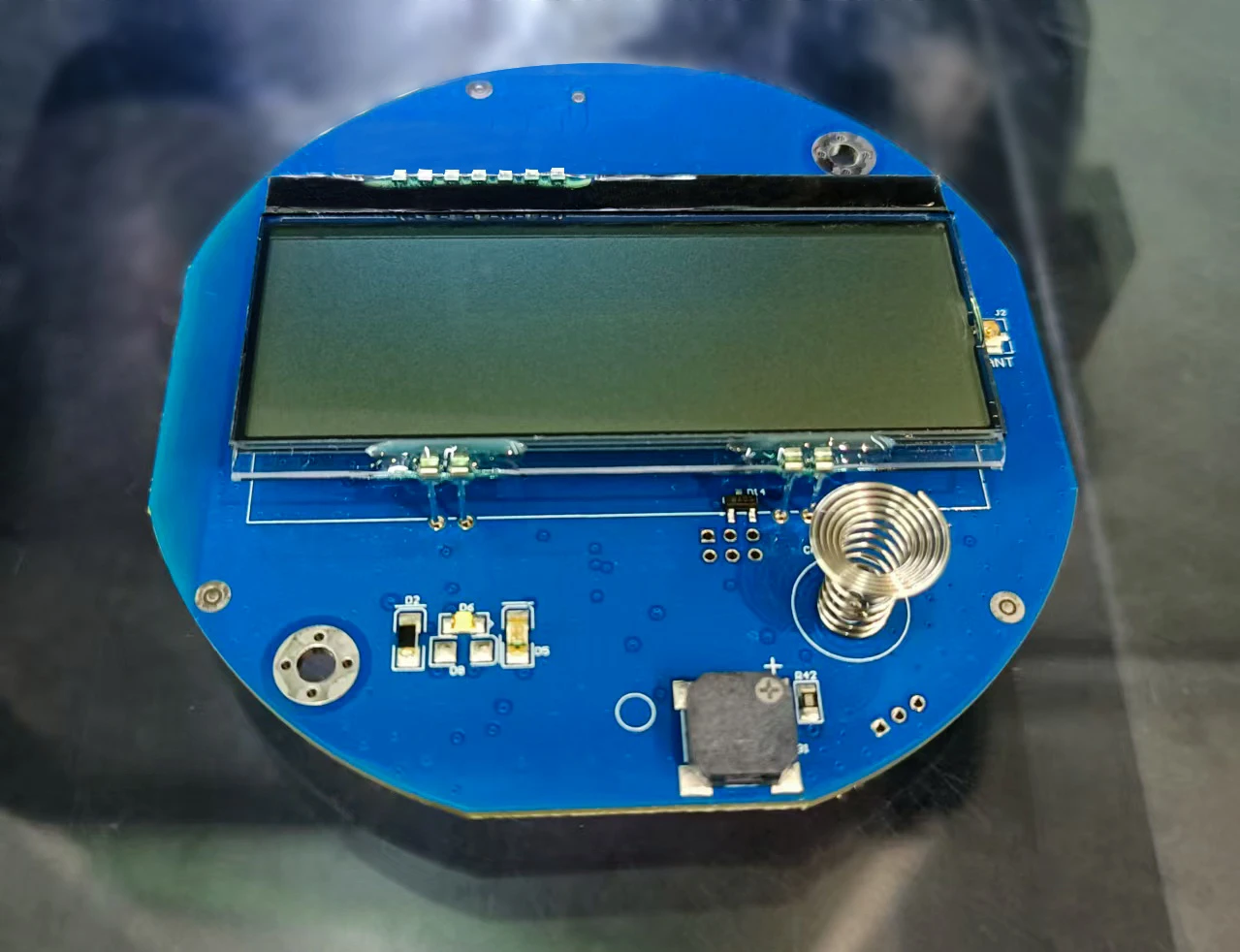
The Workpiece: Digital Ultrasonic Flowmeter PCB
The workpiece is a PCB for a digital ultrasonic flowmeter, used in the instrumentation manufacturing industry.
The PCB is part of a mating relationship with two other workpieces. The holes on the PCB are related to the positioning and fitting of these components.
If the hole positions are inaccurate, the corresponding features on the other workpieces may not align correctly, affecting how the three components fit together.
This makes hole-position measurement an important part of the dimensional inspection process.
1. What Needs to Be Measured on the PCB?
The main requirement is to measure the positional relationship between multiple holes.
PCB inspection may involve different dimensional requirements, such as:
● Hole diameter – the size of an individual hole
● Hole-to-hole distance – the spacing between holes
● Hole location – the position of a hole relative to a defined reference
● Hole pattern – the relationship between multiple holes
For this application, the focus is not simply on measuring each hole independently. The key question is whether the multiple holes are positioned correctly relative to the required reference.
2. Why Is Hole Position Measurement Important?
When a PCB needs to fit with other components, the position of its holes can directly affect the mating relationship.
For the digital ultrasonic flowmeter PCB, the board needs to fit with Workpiece 2 and Workpiece 3.
If the hole positions deviate from the required locations, the corresponding features on the other components may not align correctly. The three workpieces may therefore not fit together properly.
This means that hole position should be considered as part of the overall assembly relationship, rather than as an isolated dimensional value.
3. How Are Hole Positions Measured?
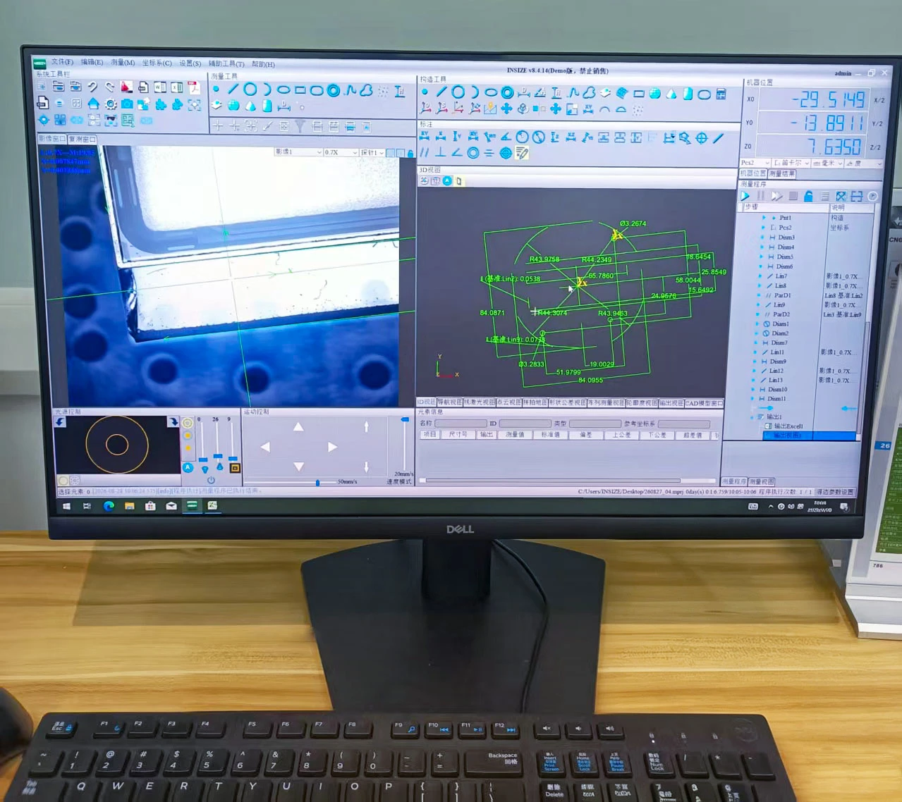
For this application, the measurement method is to establish a coordinate system based on a datum and then measure the hole positions within that coordinate system.
The basic process includes:
Step 1: Position the PCB
The PCB is placed on the measuring stage so that the required features can be observed by the optical system.
Step 2: Establish the Datum and Coordinate System
Measure the datum features as specified on the drawing, then establish the coordinate system from them.
Step 3: Measure the Holes
Measure the mounting holes to be inspected using optical imaging, as specified on the drawing.
Step 4: Evaluate the position of the holes
The positions of the multiple holes are measured within the established coordinate system, allowing their positional relationship to be evaluated.
For repeated inspection of the same PCB design, using a consistent reference can also help maintain a repeatable measurement workflow.
4. How Was This PCB Measured?
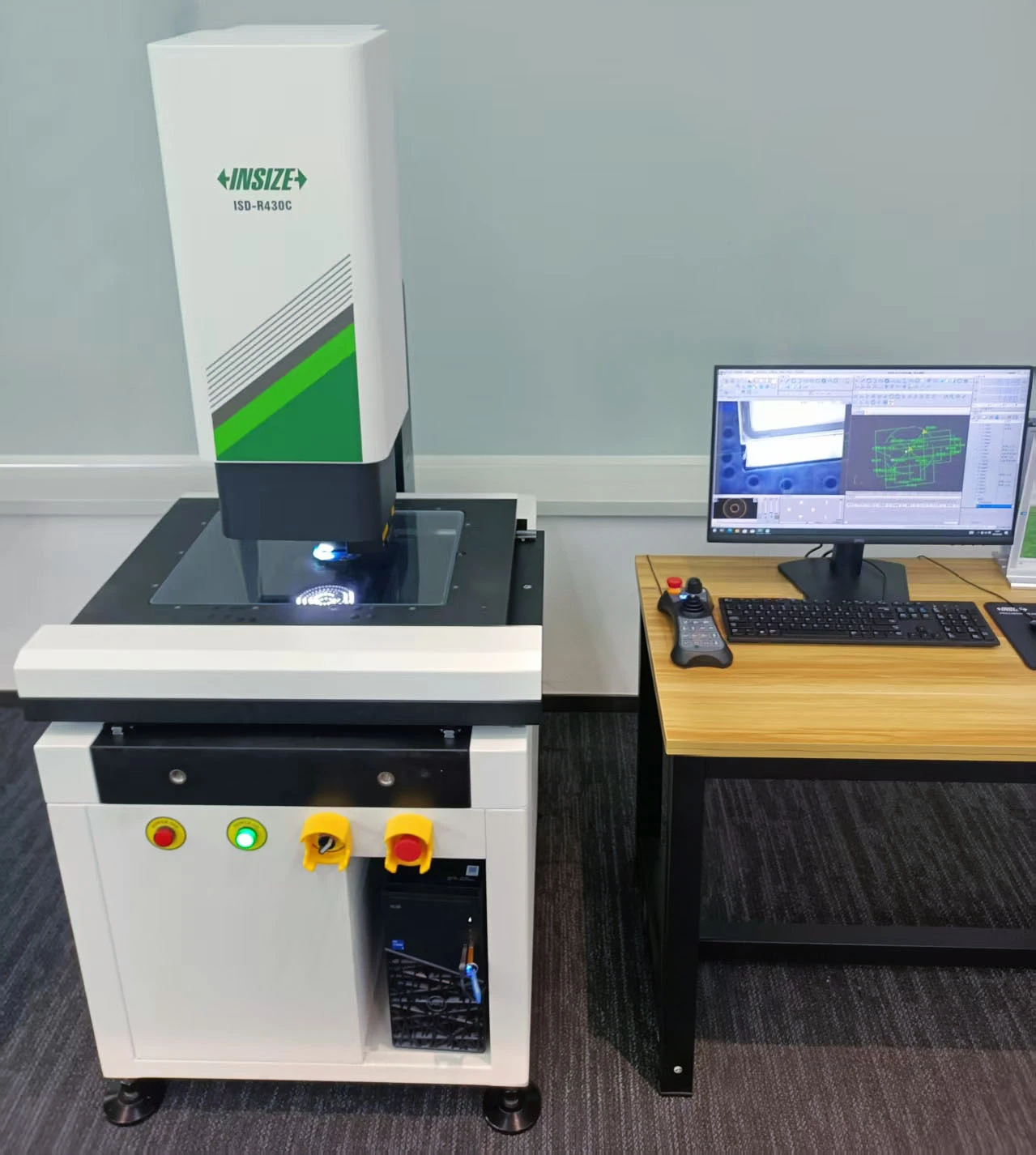
An INSIZE ISD-R430 CNC Vision Measuring System was used for this application.
The ISD-R430 provides a 400 × 300 × 200 mm measuring range, 0.5 μm X/Y/Z resolution, and X/Y-axis accuracy of ≤(2.5+L/200) μm.
For this PCB application, the relevant function is its ability to establish a coordinate system based on a datum and measure multiple hole positions within that reference.
The system uses a motorized zoom objective and optical imaging to observe the features being measured.
5. How Does Template-Assisted Positioning Help with Repeated Inspection?
When the same PCB needs to be inspected repeatedly, the workpiece may not be placed in exactly the same position every time.
The ISD-R series provides template-assisted positioning. When the measurement program runs repeatedly, as long as the positioning feature appears within the field of view, automatic measurement can be performed.
This allows predefined positioning features to help locate the PCB before the programmed measurement is carried out.
The system also supports CAD import programming, which can be used when programming measurements from CAD drawings.
These functions are relevant to repeated inspection where the same PCB design needs to be measured multiple times.
6. Key Considerations for PCB Hole Position Measurement
When selecting a measurement method, the first step is to define the actual measurement requirement.
What positional relationship needs to be verified?
Determine which holes need to be measured and what relationship between them needs to be controlled.
What should be used as the measurement datum?
The hole positions need to be evaluated against a consistent reference. Suitable datum features should be selected according to the drawing requirements.
Does the measuring range fit the PCB?
The measuring system needs to accommodate the PCB size and the location of the features being inspected. The ISD-R430 provides a 400 × 300 × 200 mm measuring range.
Is the measurement accuracy suitable?
The required accuracy should be determined by the dimensional tolerances and assembly requirements of the actual PCB rather than by equipment specifications alone.
Conclusion
For a PCB used in an industrial instrument, hole-position measurement can be closely related to the final assembly of multiple components.
In this digital ultrasonic flowmeter PCB application, the key requirement is to measure the positional relationship between multiple holes. Establishing a coordinate system based on a datum provides a consistent reference for evaluating these positions.
For repeated inspection, template-assisted positioning can further support a more consistent measurement process.
The key is to start with the workpiece, measurement features, positional relationship, and assembly requirement, and then select a suitable vision measurement method based on those requirements.